 USD
USD Euro
Euro British Pound
 Australian Dollar
- Home
-
Categories
- Car Diagnostic Tools
- Original Brand Tools
- Car Key Programmers
- OBD2 Code Scanners
- Truck Heavy Duty Scanners
- ECU Chip Tuning Tools
- Odometer Correction Tools
- VAG Diagnostic Tool
- Original Launch X431 Tools
- Original Autel Tool
- Original Xhorse Tool
- Key Cutting & Locksmith Tools
- Airbag/Service Reset Tools
- OBD2 Cables and Connectors
- AUGOCOM Camshaft Engine Timing Tool
- Other OBDII Vehicle Tools
- Car Key Blanks
- Car Key Chips
- Car Diagnostic Software
- Automotive Electrical Testers & Test Leads
- Auto HID Xenon Light and LED Light
- Automotive Electronics
- Repair & Maintenance Tools
- MB Star Diagnostic Tools
- Health Care
- Special Deals
- Consumer Electronics
- Home & Garden
- Outdoor
- Expired Tools
- Top Selling
- New Arrivals
- for MB
- for Porsche
- Xhorse
- for TOYOTA
- for FORD
- Order Tracking
- Drop-ship
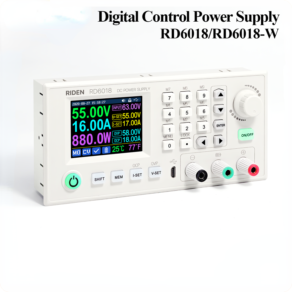

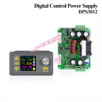
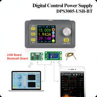
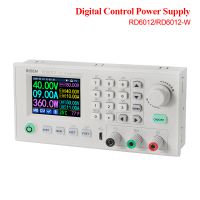
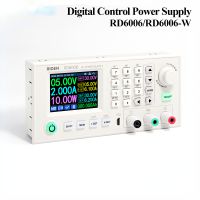
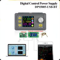
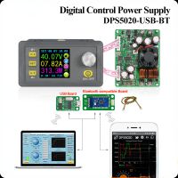
RD6018 RD6018W 60V 18A USB WiFi DC DC adjustable Step Down voltage bench Power Supply Buck converter & 800W1000W AC DC PSU
- Price:
- US$98.13/ piece
- Discount Price:
- US$79.00/ piece 19%
- Quantity:
-


- Shipping:
- Express Shipping Service
Estimated delivery time: 3-15 working days.See details » - Returns:
- Return for refund within 7 days,buyer pays return shipping.Read details »
- Support:
-
 Online Chat
  WhatsApp
  Skype
Skype  Ask a question


- Product Details
- Product's Reviews
- Write a Review
- Related Products

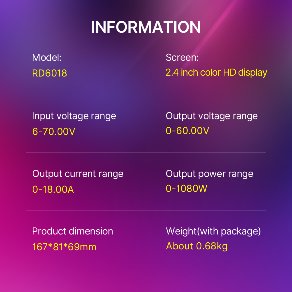
Model: RD6018/RD6018-W
Input voltage range: 6-70.00V
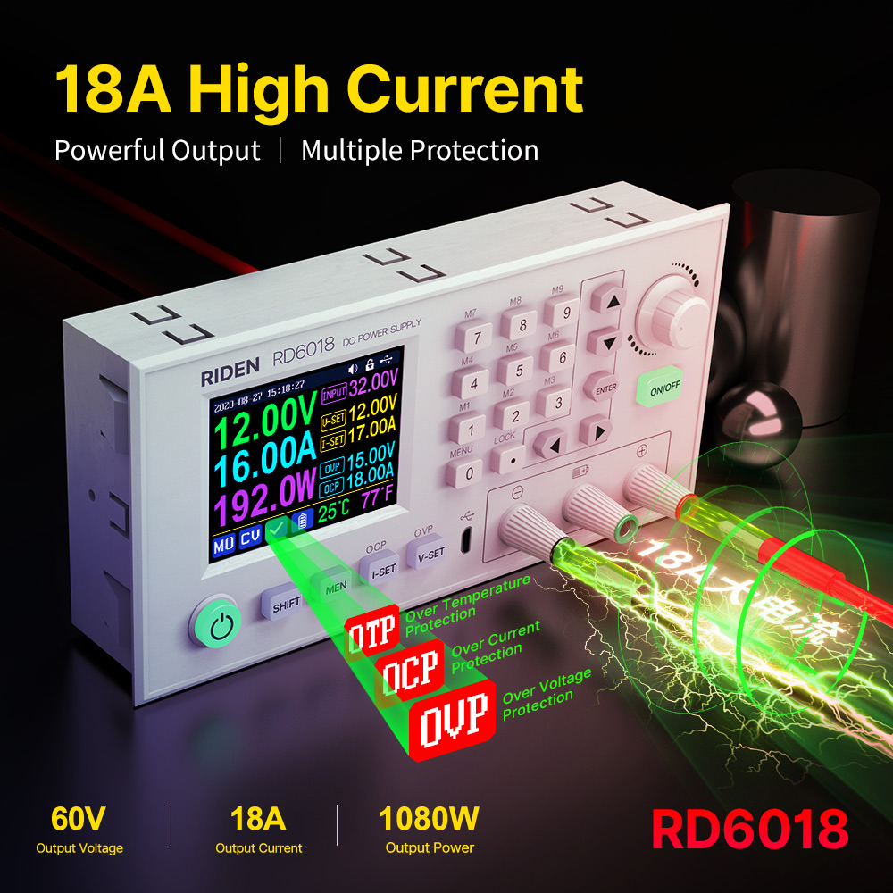
Output voltage range: 0-60.00V
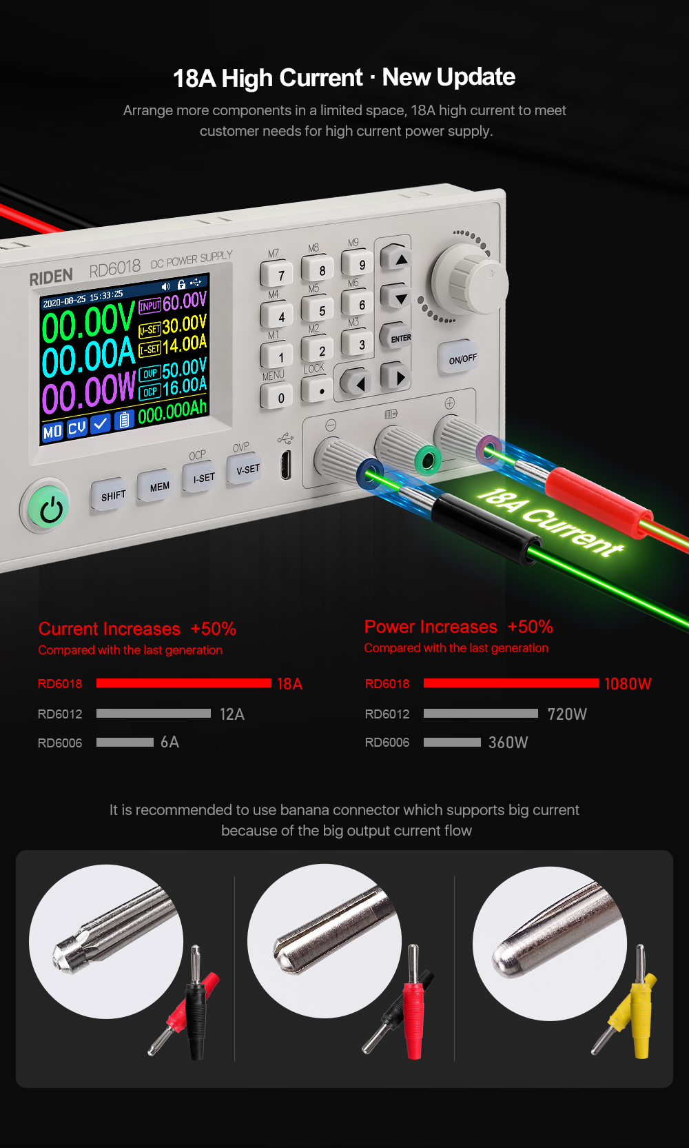
Output current range: 0-18.00A
Output power range: 0-1080W
Input voltage measurement resolution: 0.01V
Output voltagesetting measurement resolution: 0.01V
Output current setting measurement resolution: 0.01A
Battery voltage measurement resolution: 0.01V
Input voltage measurement accuracy: ±(1%+5 digits)
Output voltage accuracybetween setting and measurement: ±(0.3%+3 digits)
Output currentaccuracybetween setting and measurement:±(0.5%+5 digits)
Battery voltage measurement accuracy: ±(0.5%+3 digits)
Automatic cut off current valuewhen charging:100mA
Output ripple typical:250mV VPP@6A
Working temperature range: -10℃~40℃
External sensor Temperature detection range:-10℃~100℃/0℉~200℉
External sensor Temperature detection accuracy:±3℃/±6℉
Constant voltage moderesponse time: 2ms(0.1A-5A Load)
Constant voltage mode load regulation: ±(0.1%+2 digits)
Constant current mode load regulation: ±(0.1%+3 digits)
Capacity measurement range: 0-9999.99Ah
Energy measurement range: 0-9999.99Wh
Capacity and energy statistical error: ±2%
Buck working mode: Voltage drop >1V and >10%
Over temperature protection: System temperature>80℃
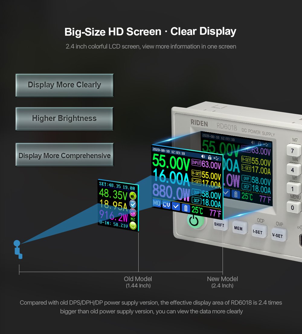
Screen brightness setting: 0-5(6 level in total)
Screen: 2.4inch color HD display
Weight(with package):About0.68kg
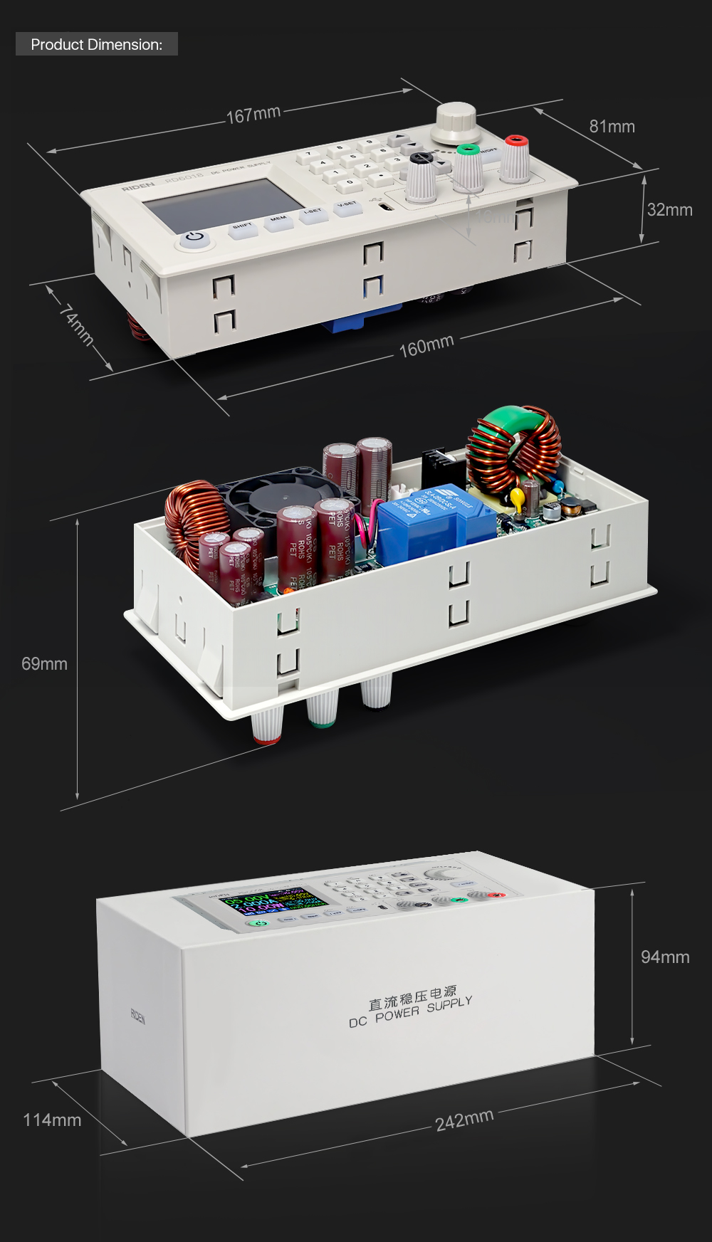
Product dimension: 167*81*69mm
Cooling fan start condition:Output current>8AorSystem temperature>45℃
Cooling fan shut down condition:Output current<7.9Aand System temperature<45℃


1,Instruction:
RD6018(W) operation instructon, PC software instruction , APP instruction ,APP and PC software download link:
A: Main download llink :https://drive.google.com/drive/folders/1V0l6P1sIJilN1yBOsTO9YGLVdkuO0cX9?usp=sharing
B: Mediafire:http://www.mediafire.com/folder/xc2v831oqj98g/RD6018
2,APP Download:
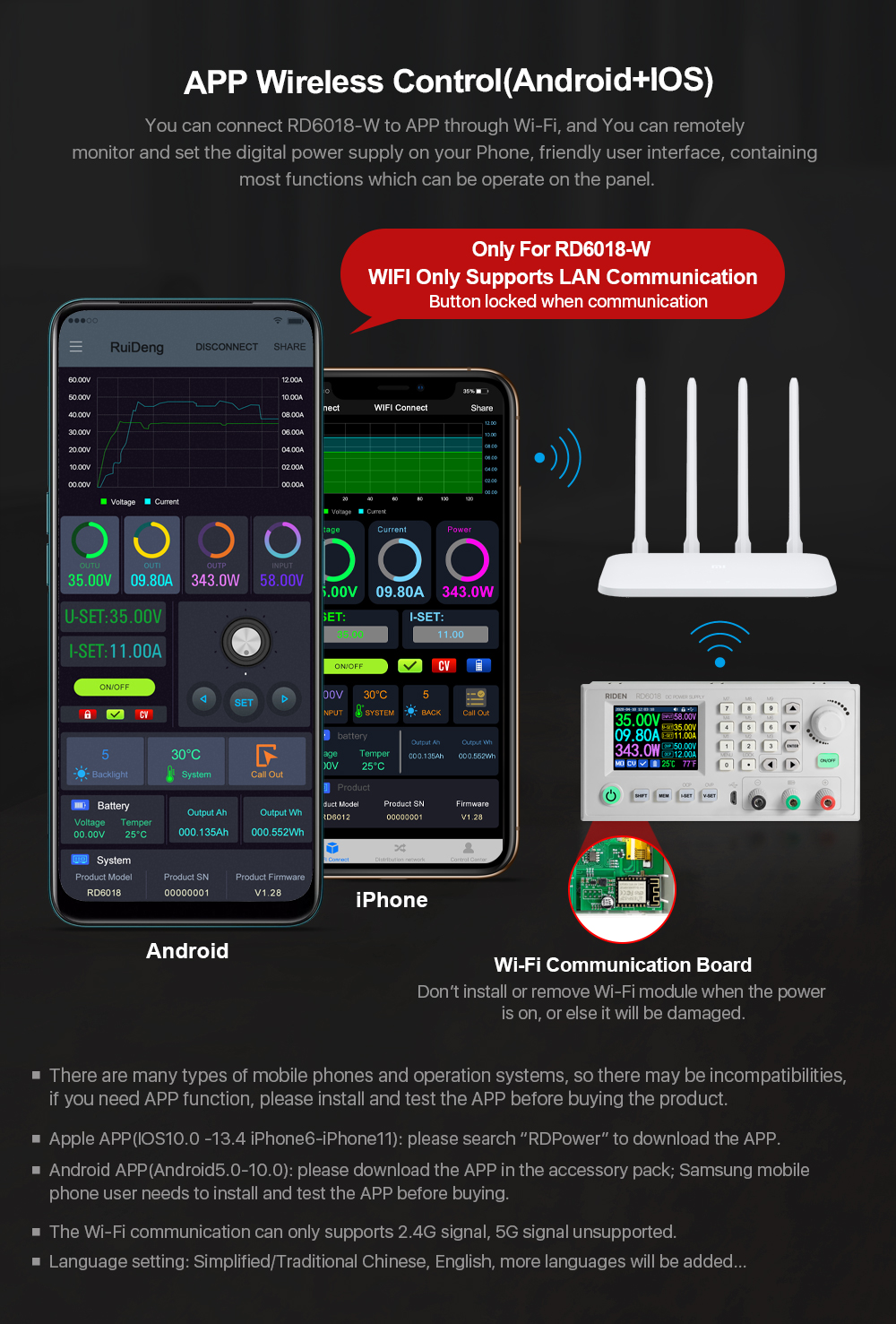
Android APP: download at file link:https://drive.google.com/drive/folders/1V0l6P1sIJilN1yBOsTO9YGLVdkuO0cX9?usp=sharing, Support android 8.0 -android 10.0;
Android APP Google Playdownload:Search "Ruideng" to download , support Android 8.0 and above phone
IOS APP download: Search "RdPower" to download , support IOS10.0-IOS13.4 System
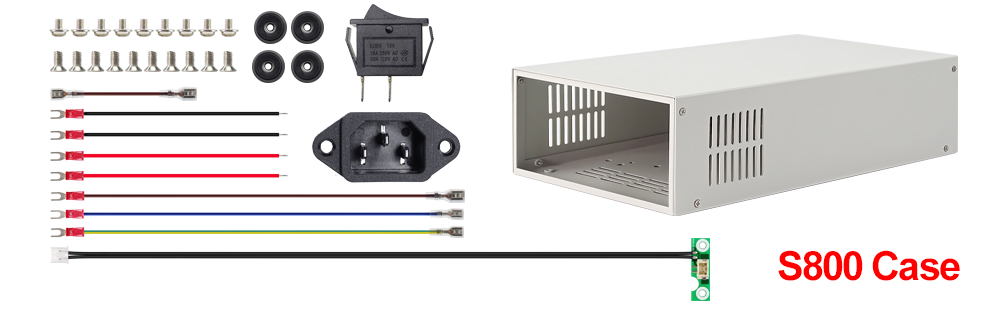
3, Case Assembly:
RD6018 and S800 caseassemble instruction:https://drive.google.com/drive/folders/11Zb8hHO2ABnWO-Com304y0jQPFi8VTO7?usp=sharing

1,Instruction video:
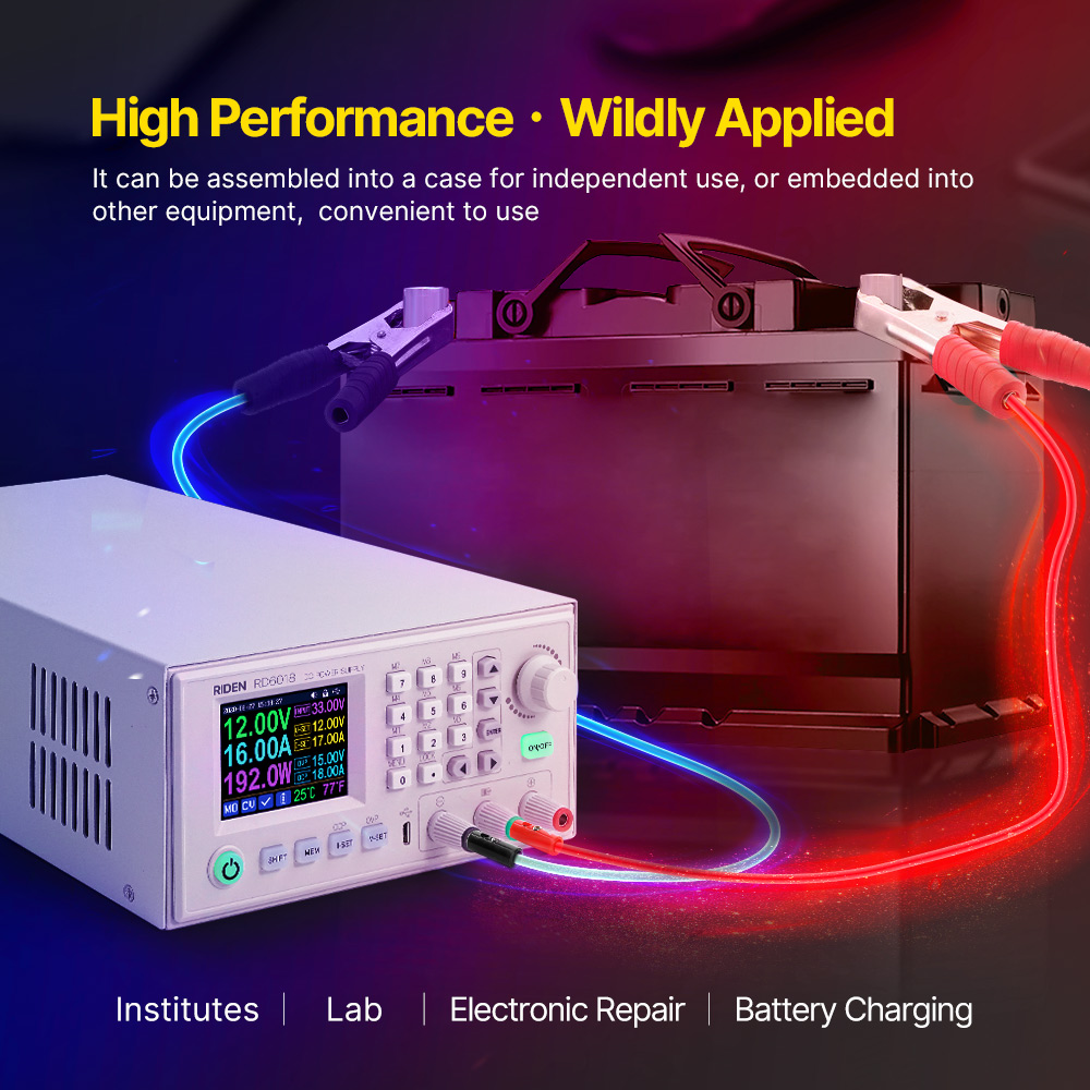
a.section 1.4.2.1Battery Charging Function Introduction:https://youtu.be/irTbqfqtgU0
b.section 1.4.2.2Output Voltage and Output Current Setting:https://youtu.be/S6Kan66dNsk
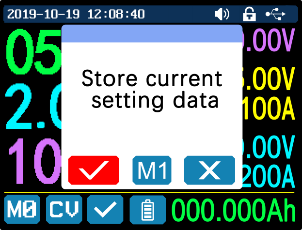
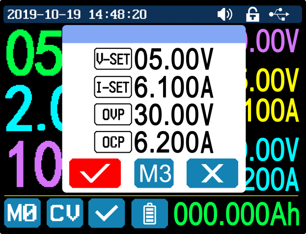
c.section 1.4.2.3Data Group Quick Storage and Call out:https://youtu.be/eo5saPjOGpo
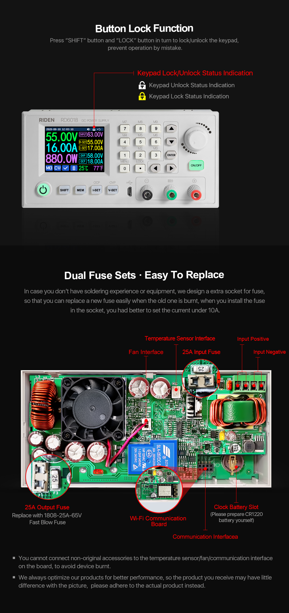
d.section 1.4.2.4Keypad lock and unlock:https://youtu.be/zxpmasJyQ6Y
e.section 1.4.2.5System Setting:https://youtu.be/Q9d3rIgIrOc
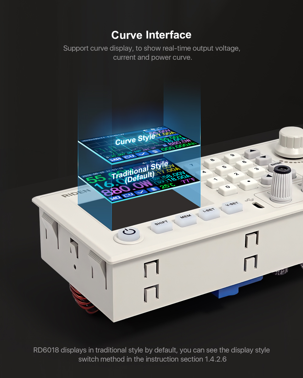
f.section 1.4.2.6Main Page Style Setting:https://youtu.be/f51VDiY2VHE
g:section 1.4.2.7Storage Data Setting:https://youtu.be/i1kTeurS13I
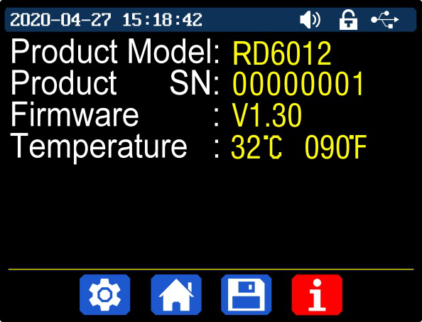
h:section 1.4.2.8System Information:https://youtu.be/Um4NQObeeJE
i:section 2.1.2IOS APP Download, Installation and Connection:https://youtu.be/nH2HYwop0TE
j:section 2.4.2IOS APP Operation:https://youtu.be/lXSw1CM9IY8
k:section 3.1.1/3.2.3.2Android APP Download, Installation and Connection:https://youtu.be/QwyBEUCnp9c
l:section 3.2.3.3Anroid APP Operation:https://youtu.be/hqrF4keTfbE
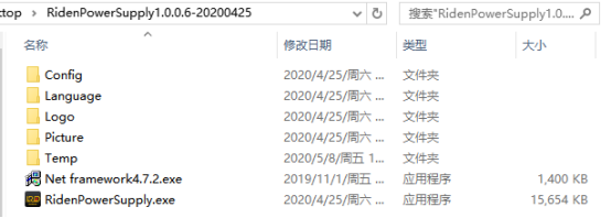
m:section 4.1/4.3.1PC Software Download and basic operation:https://youtu.be/mjt1RMaah1Y
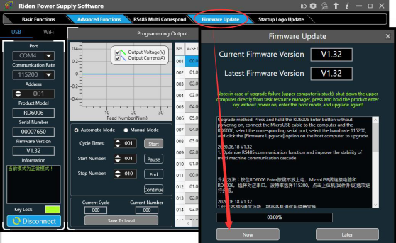
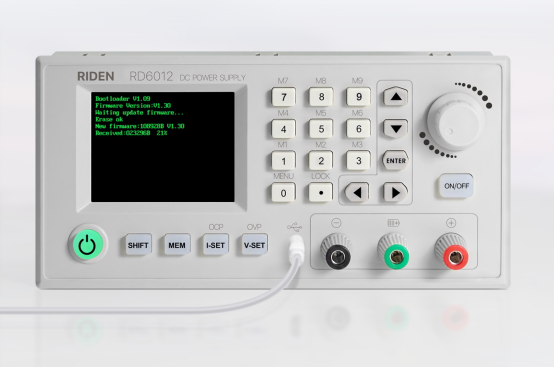
o:section 4.3.2Firmware Upgrade:https://youtu.be/NOoLfDw0DiY
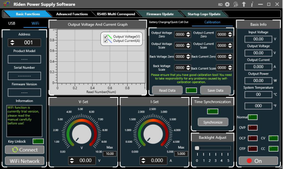
p:section 4.3.3Calibration:https://youtu.be/c9sn1wY2mjE
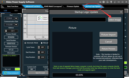
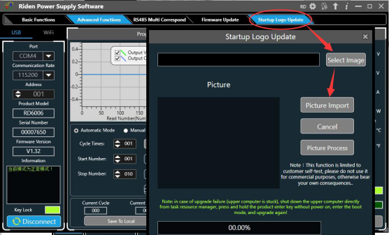
q:section 4.3.4Logo Update:https://youtu.be/vuVhBsohWts
r: RD6006 wifi connection Problem and solution:https://www.youtube.com/watch?v=7sTtc1kweJM
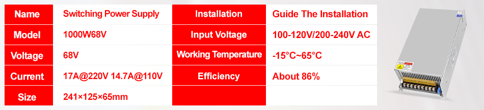
2,PSU Notification
If you order the PSU, after getting the PSU, please use multimeter to check if the real output voltage is stable and fits the rated voltage, to see if it is damaged on the way, if the output is abnormal, please contact us, do not connect it to RD power supply to avoid more loss
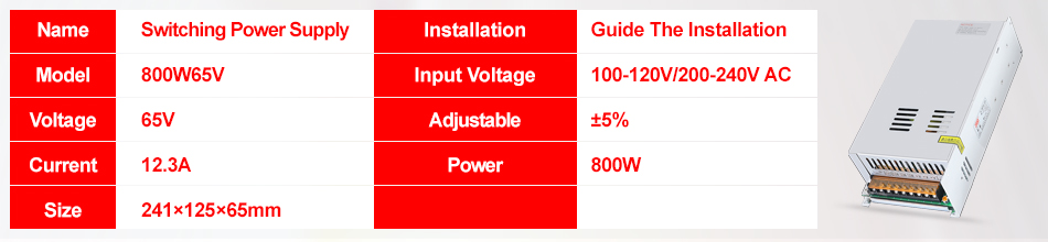
800W PSU can let RD6018 output 60V or output 18A, but it cannot let RD6018 full output 60V 18A at the same time, because it is lower than the max output power of RD6018(1080W)
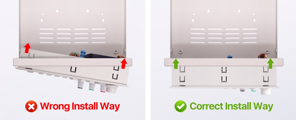
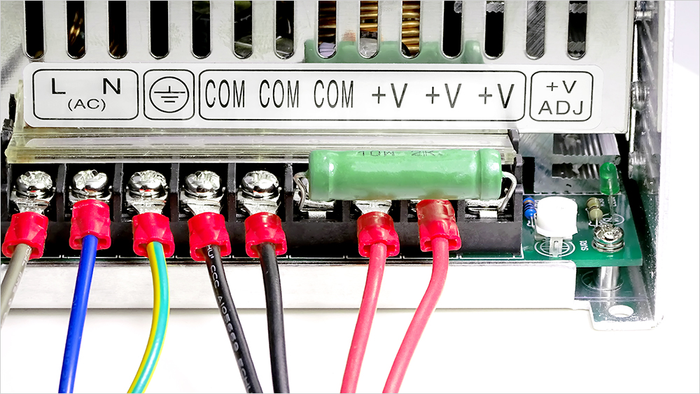
3,Assembly Notification
You can only connect the cables with a foundation in electronic and electrical engineering and it must be reliably grounded!
4,Correct Installation
5, Actual Test Video

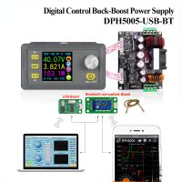
1. Q: What is the differences between RD6018 and RD6018-W?
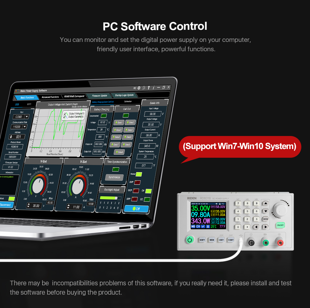
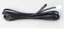
A: RD6018-W has WIFI board , RD6018 doesn't have. RD6018-W can use WIFI board to connect APP, also use USB micro cable to connect PC software . RD6018 doesn't have WIFI board, only support PC software by connecting with USB micro cable, no support APP.
2. Q: What can I get in this link?
A: the option title and pictures shows what you can get, please check and make the order.
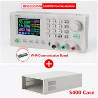
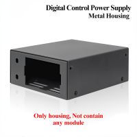
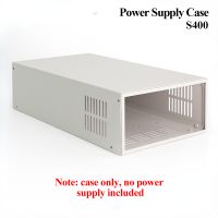
3. Q: What does S800 case contains?
A: For S800 case, it is just case, not containing any power supply, it contains the internal cables and screws, it is suitable for RD6012/RD6018/RD6024 and AC-DC 800W/1000W switching power supply, you can buy them separately to assemble then together.
4. Q: Why the product I get is a bit different with the picture?
A: We keep updating the product hardware and software to make the device better, so the internal material details may be different, but it does not affect you to use the functions.
5. Q: why does the instruction not come with the product?
A: Because the products keep updating, we will add some function with the firmware and hardware update, so you can download the instruction online.
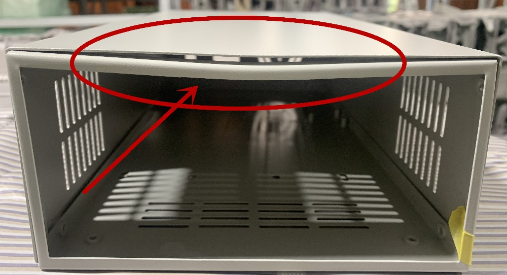
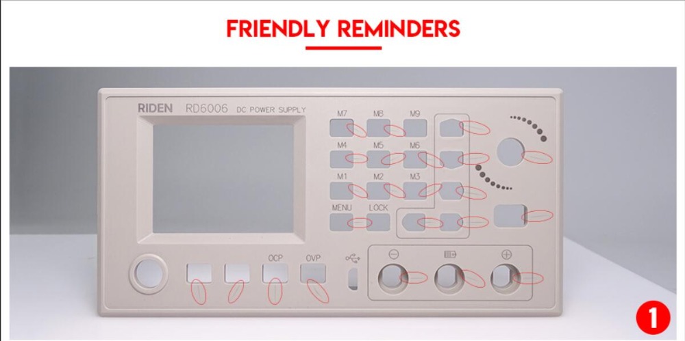
6. Q: the case I receive is a bit deformed?
A: For the case, during the shipping,maybe the case side will be a little deformed (just like picture ), you can use your hand to adjust, that's OK, if you mind this , please stop buying.
7. Q: the PSU I receive have some scratches?
A: There may be scratches on the surface but it doesn't affect the product performance, please do not be over picky, and if you do mind this, please do not buy this product
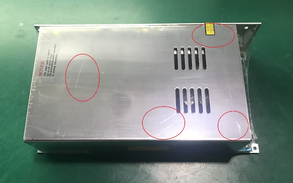
8. Q: the warranty label is broken, do I still get the warranty?
A: Due to express delivery, some power supply warranty labels may be damaged, which does not affect product warranty!
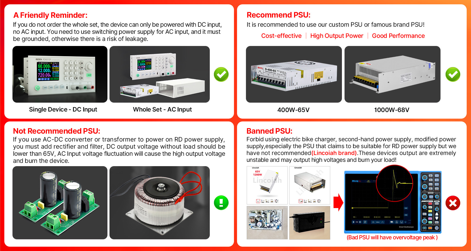
9.Q: How do I choose the PSU?
A:Friendly reminder, If you do not order the whole set, the device can only be powered with DC input, no AC input. You need to use switching power supply for AC input, and it must be grounded, otherwise there is a risk of leakage.
AA: Recommend PSU
It is recommended to use our custom PSU or famous brand PSU!
BB: Not recommended PSU
If you use AC-DC converter or transformer to power on RD power supply, you must add rectifier and filter, DC output voltage without load should be lower than 65V,power grid voltage fluctuation will cause the high output voltage and burn the device!
CC. Banned PSU
Forbid using electric bike charger, second-hand power supply, modified power supply, especially the PSU that claims to be suitable for RD power supply but we have not recommended ......These devices output are extremely unstable and may output high voltages and burn your load!
(bad PSU will have peak over-voltage)
11.Q: Can I use it to power on inductive load?
A: If you connect inductive load (such as motor), the max working current is 1/3 of range. don't exceed it.
12. Q:why there is a fuse in the box? Should I install it?
A:It is a BACKUP fuse in the, if you burn the fuse with wrong operation, you can insert the fuse in the socket next to the burned one for temporary use and it supports only 10A, so it is better to remove the damaged fuse and solder the good fuse on the same position for full output.
13. Q: can I remove the case of the PSU for better heat dissipation?
A: when install our PSU into the case, please follow our instruction to assemble, do not remove the shell of the PSU to use. After removing the shell of the switching power supply, the structural change of the heat dissipation system will lead to insufficient heat dissipation,and some components will be overheated and damaged, in this case we don't offer after sell service
14. Q:Does the 800W65V PSU has high-frequency noise?
SOFTWARE QUESTIONS:
1. Q: The APP crashes on my phone, what the problem is?
A: For APP and PC software, because there may be incompatibilities problems, please download first before buying , if you can download and install, you can make order, or else stop buying. If you don't test the PC software and APP function before buying and find that the products works fine except the PC software or APP, we refuse to refund.For PC software, it only support win 7 and above for now. For APP, it only support android 8.0 and above.
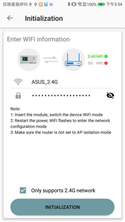
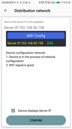
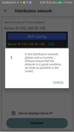
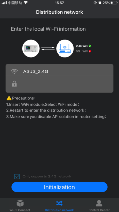
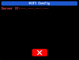
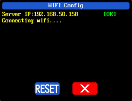
2. Why cannot I connect the RD6018W to my phone APP via WIFI?
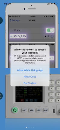
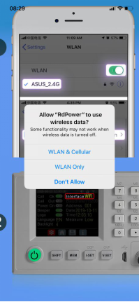
A: Please check if the WIFI board is inserted properly, then check if the WIFI is 2.4G Hz and if you shut down the client isolation/ AP isolation and WMM function, and check if you turn on the location service and storage service when you install the APP. If there is still problem, contact us.
3.Why cannot I connect the RD6018W to PC via WIFI while I can connect to the Phone?
A:WiFi connection is a test function, due to poor compatibility of some computers, if you cannot connect PC software via WiFi, please ignore this function. Forthis function, we do not provide any guarantee and technical support, and we will decide whether to keep this function based on customer feedback.

| Model | ||||||
| Input voltage range | 6-70.00V | 7-70.00V | 7-70.00V | 6-70.00V | ||
| Output voltage range | 0-60.00V | 0-60.000V | 0-60.000V | 0-60.00V | ||
| Output current range | 0-6.000A | 0-12.00A | 0-18.00A | 0-6.0000A | 0-6.0000A/ 0-12.000A | 0-24.00A |
| Output power range | 0-360W | 0-720W | 0-1080W | 0-360W | 0-720W | 0-1440W |
| Output voltage setting measurement resolution | 0.01V | 0.001V | 0.01V | |||
| Output current setting measurement resolution | 0.001A | 0.01A | 0.0001A | 0.001A/ 0.0001A | 0.01A | |
| Output voltage accuracy between setting and measurement | ±(0.3%+3 digits) | ±(0.5‰+4 digits) | ±(0.3%+3 digits) | |||
| Output current accuracy between setting and measurement | ±(0.5%+5 digits) | ±(1‰+6 digits) | ±(0.5%+5 digits) | |||
| Automatic cut off current value when charging | 10mA | 100mA | Set by yourself | Set by yourself | Set by yourself(higher than 100mA) | |
| Output ripple typical | 100mV VPP | 250mV VPP@6A | 20mV VPP | 100mV@12A,150mV@24A VPP | ||
| Buck working mode | Voltage drop >1V and >10% | (input voltage÷1.1)-2 | (input voltage÷1.1)-1 | |||
| Weight(with package) | About 0.58kg | About 0.61kg | About 0.68kg | About 0.62kg | About 0.66kg | About 0.72kg |
| Product dimension | 167*81*65mm | 167*81*69mm | 167*81*65mm | 167*81*69mm | ||
20MHz of bandwidth on your oscilloscope with a 0.1uF parallel capacitor at the output terminals
②for example: input voltage is 24V,the max output voltage is 19.8V.

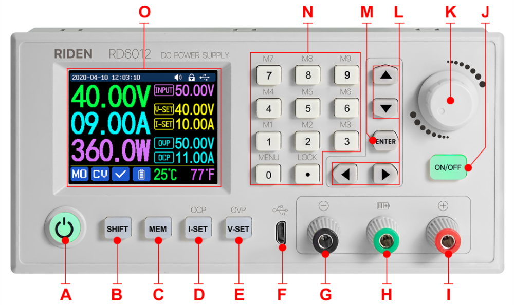
| A: Power button | B: SHIFT Second function button |
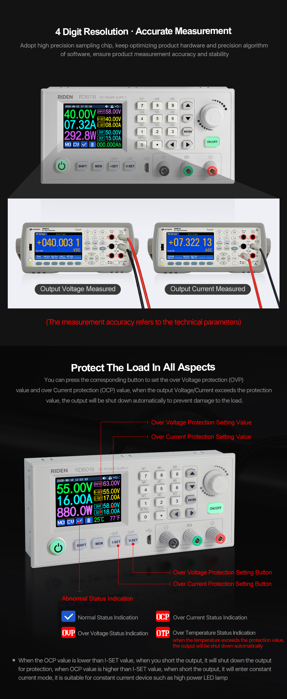
| C: Quick storage button | D: Current/Over current protection setting |
| E: Voltage/Over voltage protection setting | F: Micro USB port |
| G: Power supply output negative terminal/ Battery charging negative terminal | H: Battery charging positive terminal (Dedicated terminal for battery charging) |
| I: Power supply output positive terminal | J: Output switch |
| K: encoder potentiometer/Cancel button | L: Direction button |
| M: Enter/ Confirm button | N: keypad |
| O: Screen | |
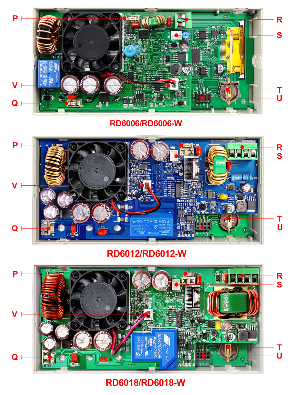
| P: Input fuse | Q: Output fuse |
| R: Power source input interface | S: External temperature sensor interface |
| T: CR1220 battery socket | U: Communication module interface |
| V: Fan interface | |
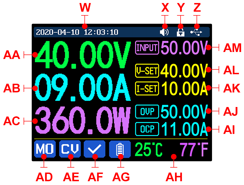
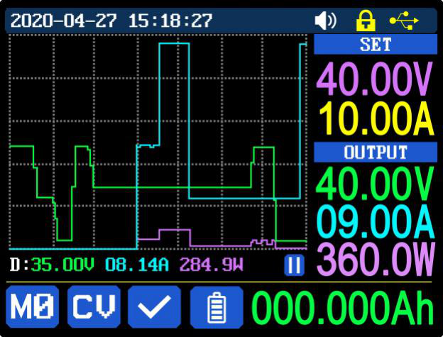
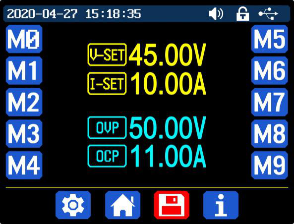
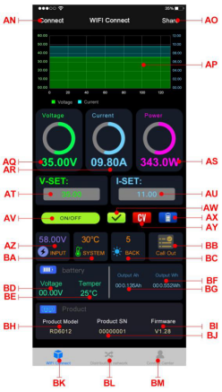
| W: Time | AF: Protection status indication |
| X: Button tune | AG: Battery charging indication |
| Y: Button lock status | AH: Battery related information display area |
| Z: Communication interface | AM: Input voltage |
| AA: Actual output voltage value | AL: Output voltage preset value |
| AB: Actual output current value | AK: Output current preset value |
| AC: Output power | AJ: Over voltage protection value |
| AD: Current data group | AI: Over current protection value |
| AE: Constant voltage Constant current status | |
 displayed on the top (cannot unlock manually), and the keypad will be automatically unlocked when the connection disconnected manually, there will be
 displayed, the keypad will be automatically unlocked when the connection disconnected abnormally, and the power off button can be used when the keypad is locked.
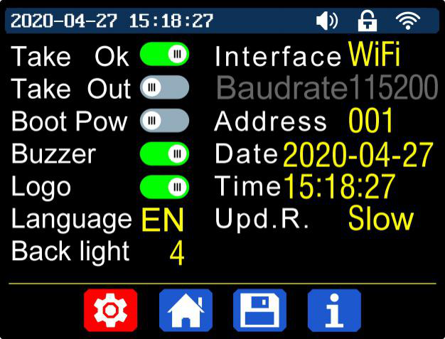
 on the top. If you turn it off, there will not be button tune when press the button, and there will be
 on the top.
 on the top when communication starts.Wi-Fiinterface is the Wi-Fi module inserted to the communication interface, you can see the
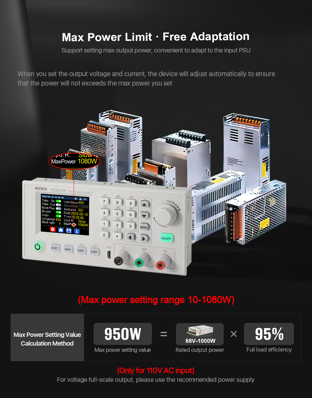
 on the top when communication starts (connect mobile phone by Wi-Fi, WiFi function only support connection control in LAN),TTLis not available for the time being; When the interface is changed, you need to reboot RD6006 to apply the modification. The baud rate can be set to 9600/19200/38400/57600/115200 under USB mode; The Baud rate under Wi-Fi is fixed at 115200. Device address can be set from 001-255. You can set the date and time by rotating the encoder potentiometer, the setting will be saved immediately after modification. Please do not set a wrong time, it may cause that the date will not be automatically accumulated. Press the encoder potentiometer to return, and the set value will be saved automatically.Upd.R.is the refresh rate of read back voltage and current in the main page, you can set it to low, middle and high. We add output power limit function, when you set that, the current will be adjusted automatically to the value which multiply by set voltage value will not exceed the power limit, so that it can protect the input PSU, it is recommended to set the output power value at (rated power of PSU*95%). Press encoder potentiometer to return and save the settings.
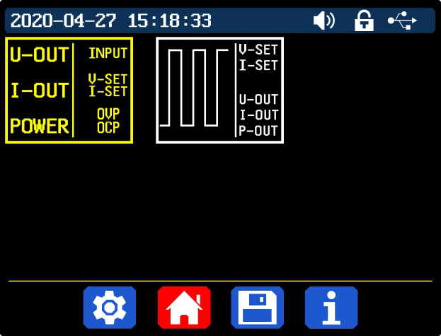

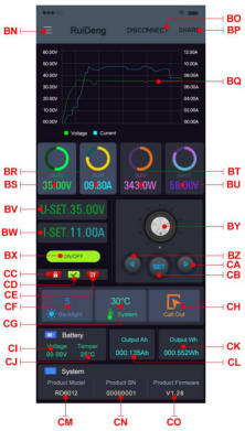
| BN: call out/ shut down sidebar | CB: set button |
| BO: connection button | CC: keypad lock indication |
| BP: export data to mobile phone folder | CD: protection status indication |
| BQ: data curve | CE: constant voltage/ constant current status |
| BR: actual output current | CF: screen brightness |
| BS: actual output voltage | CG: system temperature |
| BT: actual output power | CH: data group quick call out |
| BU: input voltage | CI: battery voltage |
| BV: preset voltage value | CJ: external sensor temperature detecting value |
| BW: preset current value | CK: accumulated output power |
| BX: ON/OFF button | CL: accumulated output capacity |
| BY: setting wheel | CM: model being connected |
| BZ: move the cursor to the left | CN: product SN number |
| CA: move the cursor to the right | CO: product firmware version |
 |  |
| Picture 3 | Picture 4 |
 |  |
| Picture 5 | Picture 6 |
 |  |
| Picture 7 | Picture 8 |

| AN: connection button | BA: system temperature |
| AO: export data to mobile phone folder | BB: data group |
| AP: data curve | BC: screen brightness |
| AQ: actual output voltage | BD: battery voltage |
| AR: actual output current | BE: external sensor temperature detecting value |
| AS: actual output power | BF: accumulated output power |
| AT: preset voltage value | BG: accumulated output capacity |
| AU: preset current value | BH: model being connected |
| AV: output ON/OFF button | BI: product firmware version |
| AW: protection status indication | BJ: product SN number |
| AX: battery status indication | BK: main page |
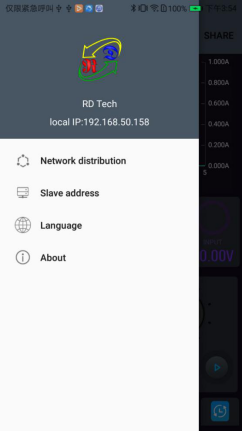
| AY: constant voltage/ constant current status | BL: network distribution page |
| AZ: input voltage measurement value | BM: personal center |
 |  |
| Picture 9 | Picture 10 |
 |  |
| Picture 11 | Picture 12 |
 |  |
| Picture 13 | Picture 14 |
 |  |
| Picture 15 | Picture 16 |
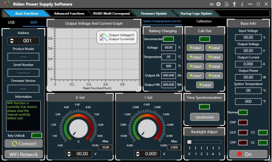
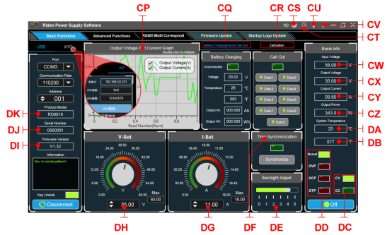
| CP: Voltage-Current Curve | DA: System Temperature(℃) |
| CQ: Battery information/ Data Group Quick Call Out | DB: System Temperature(℉) |
| CR: Calibration | DC: Constant Voltage/ Constant Current Status |
| CS: RD/DPS series switch | DD: Protection Status Indication |
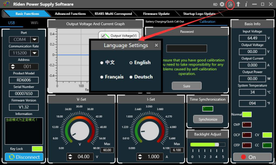
| CT: Language | DE: Screen Brightness Setting |
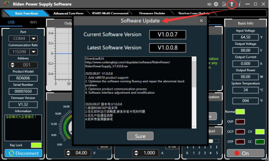
| CU: Software Update | DF: Synchronize System Time |
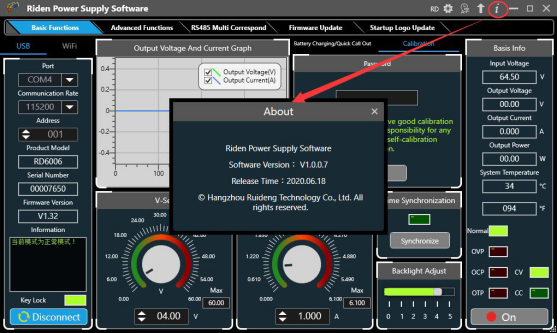
| CV: About | DG: Output Current Preset value |
| CW: Input voltage | DH: Output Voltage Preset value |
| CX: Actual Output Voltage | DI: Firmware Version |
| CY: Actual Output Current | DJ: Serial Number |
| CZ: Actual Output Power | DK: Product Model |


- Related Items
- Recommond Tools
- Hot Sale
- On Sale
- New Arrivals
- Freeshipping Items
-
 US$12.99 / piece
 -
 US$64.99 / piece
 -
 US$79.90 / piece
 -
 US$79.00 / piece
 -
 US$464.00 / piece
 -
 US$649.00 / piece
-
 US$1,299.00 / piece
 -
 US$749.00 / piece
 -
 US$39.90 / piece
 -
 US$219.00 / piece
 -
 US$109.00 / piece
 -
 US$249.00 / piece
-
 US$199.00 / piece
 -
 US$449.00 / piece
 -
 US$499.00 / piece
 -
 US$599.00 / piece
 -
US$79.90 / piece
-
 US$839.00 / piece
-
 US$469.00 / piece
 -
 US$25.99 / piece
 -
US$839.00 / piece
-
 US$84.99 / piece
 -
 US$579.00 / piece
 -
 US$13.99 / piece
-
 US$49.99 / piece
 -
 US$39.99 / piece
 -
 US$1,690.00 / piece
 -
 US$989.00 / piece
 -
US$464.00 / piece
-
 US$7.90 / piece
-
 US$27.99 / piece
 -
 US$77.90 / piece
 -
 US$265.00 / piece
 -
 US$29.99 / piece
 -
 US$725.00 / piece
 -
 US$17.99 / piece
Trending Products
 US$449.00 / piece
 US$379.05 / piece
 US$43.90 / piece
- US$109.00 / piece
 US$289.00 / piece
 US$639.00 / piece